In our previous post we took a dive into one type of 3D printing, composite printing, which is mostly used in big scale industrial printing. However, it is important to consider not only the final product, but the process which usually starts with an idea.
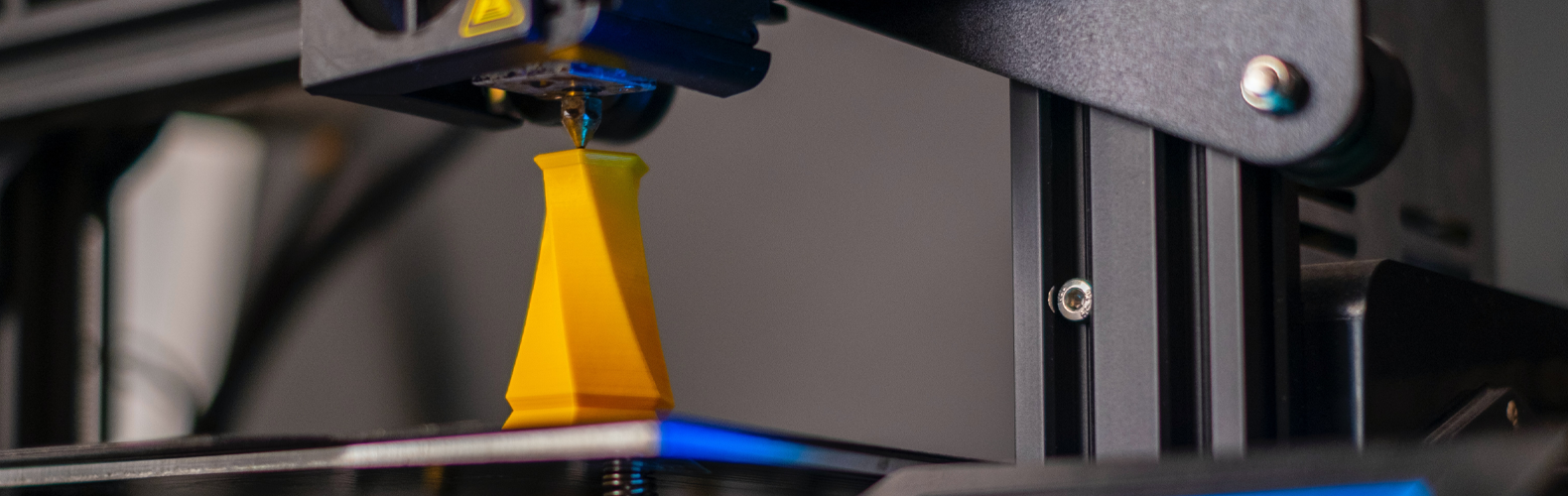
In this post we’ll be taking a look at the processes of FDM(Fused Deposition Modeling)//FFF (Fused filament fabrication) short for material extrusion method. This means that a simple solid plastic thread (filament) after being unwound from its drum, is pressed through a heating block, and then because of the pressure it gets extruded through a tapered end tube, the nozzle. The liquid plastic then solidifies, forming a layer. Layer after layer our 3D printed object takes form. The entire process has much more steps and influencing factors, but this is the essence of it. Let’s dive deeper into the details below!
Don’t be afraid to dream!
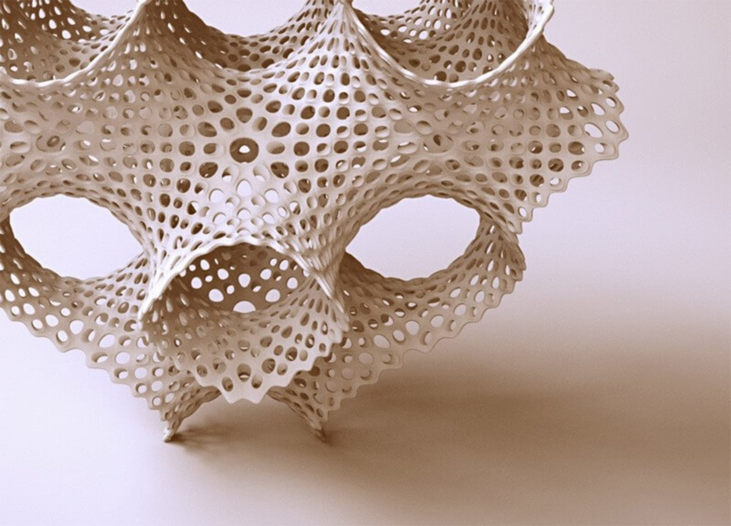
A very good starting point is if someone has an idea about a thing they want to make and bring into life by 3D printing. But even before we can begin the process, we have to think very carefully about exactly what we want to make, and how we plan on using that product. Thinking about usage is important, because it often affects the technology we’ll need to choose in order for our product to be suitable for actual use. For example, if we’d like to make a decorative sculpture it might be better to use a resin based SLA printing technology, which is more precise, rather than FDM/FFF. If we want our product to be flexible, it might be wise to use powder based laser-sintering technology, in short SLS. We can of course use any type of filament technology, but it might come with a few trade-offs.
Modeling
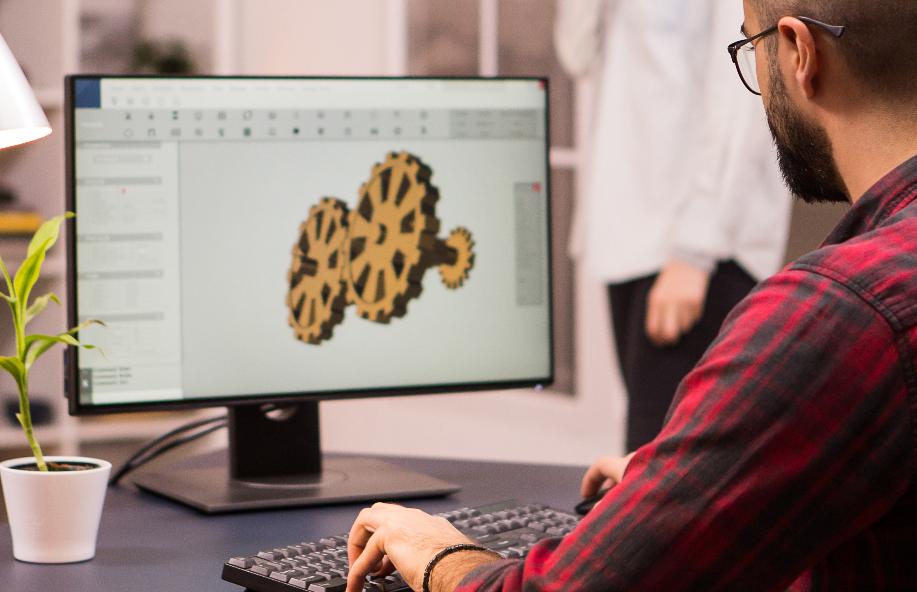
After we made sure that the ideal technology for whatever we’d like to print is indeed FDM/FFF we can start the actual work. First we need to make a 3D model of the product using a computer software. It’s best if we choose a software from which we can export an .STL file , since this is a format that slicing softwares can handle. CAD softwares can be particularly useful, as they have a load bearing test feature. Using this feature we can make simulations and examine how our product would behave under different circumstances and use cases. Depending on the results of the simulations we can modify our models as needed and we can also determine one of the most important factors of printing, the orientation.
Slicing
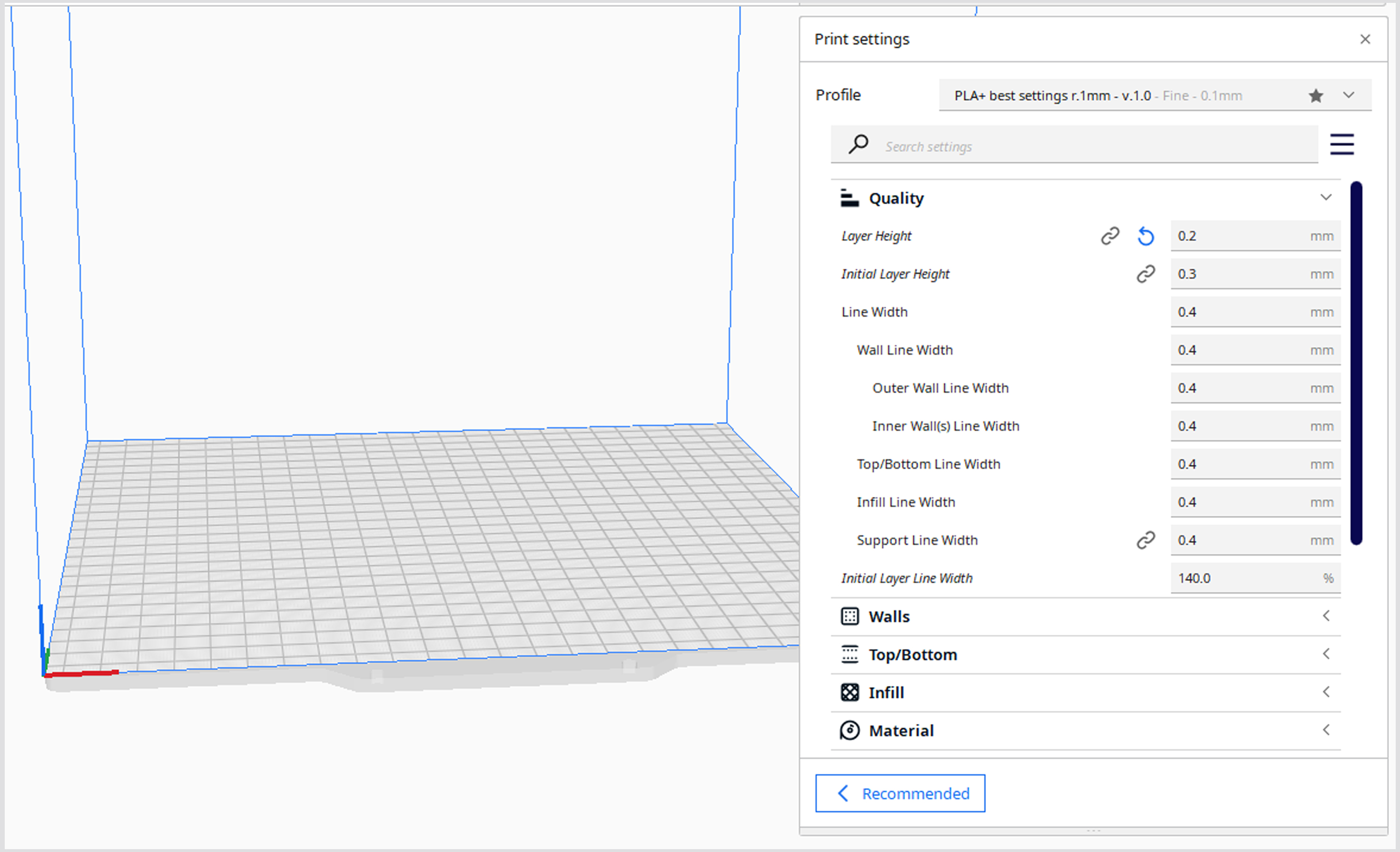
After modeling and optional simulations we have to export our model in .STL format, as it is necessary to “slice” the model before printing. These days we can choose from a variety of programs available. One of the most widespread slicer programs is the free Cura, distributed by Ultimaker.
Within the slicing software we have numerous settings available. Here are some of the essential ones:
- Layer height:This determines the surface quality of the final printed product. The bigger the value, the rougher the surface will be. It is important to note that the minimum and maximum values depend on the printer, and more precisely the nozzle the printer has. The nozzle can be changed if needed, but more about this in a later blog post.
- Wall thickness: This determines how many layers i.e. how thick the wall will be.
- Infill: This value is responsible for the density of the printed object. We can set the value in percentage. At 0% the object will be completely hollow, and at 100% the object will come out completely solid.
- Support: In some cases, because of the layering, some parts of the print would hang free in air during printing. Not even a 3D printer can perform such a miracle, but it can remedy the problem by printing an extra object, called a support, under the desired surfaces, which supports the otherwise unsuspended surface. This support can be removed relatively easily later.
- Printing speed: We can set the velocity of movements during printing done by the printing nozzle in mm/s.
- Printing and printing bed temperature: It is very important to determine the temperature of both the printer head and the printing bed. The former affects the quality of the print and the latter plays a role in the adhesion of the printed object to the printing bed. (There are printers with non-heatable printer beds, in those cases, we can’t dial this in.)
- Printing bed adhesion: We can add extra surface layers, which help adhesion to the printing bed and in some cases, make for better heat distribution thus decreasing the chance of deformation.
In addition to these, we can access a lot of other settings if we turn on the advanced mode in the slicer, but perhaps we will dedicate a separate post to that later.
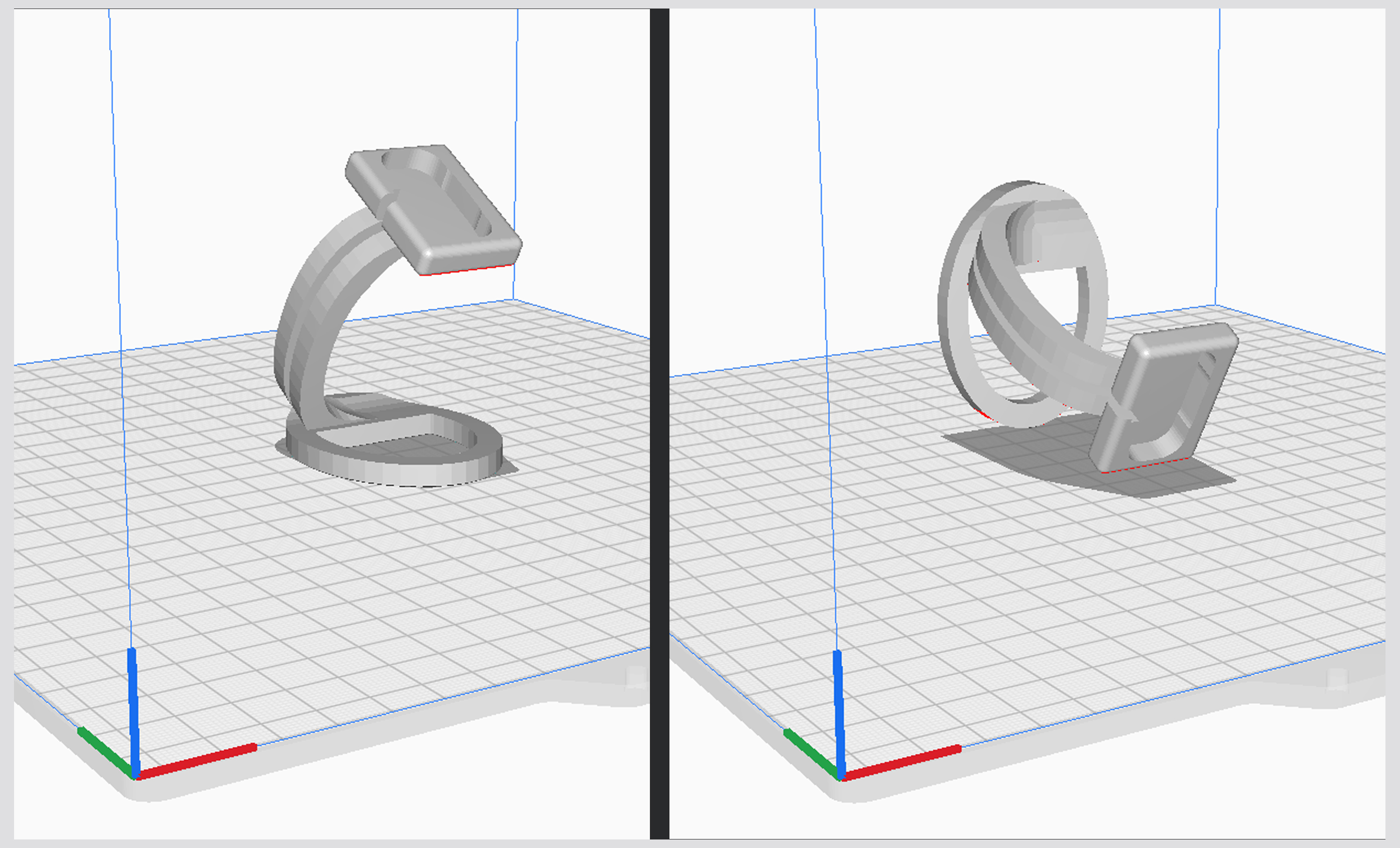
It is important to take a closer look at the orientation of the print, that is, on which of its surfaces the model should lie on the table. This is primarily determined by the use of the printed object, because between the layers, along the Z axis, a much weaker bond is formed than along the X-Y axes. In conclusion, if the majority of the load on the final product will be in that direction, the object will most likely break very easily, along the layers, as there is no chemical bond between them, only a physical one. Secondly, it is determined by the need for supports, if the object lays on one of its surfaces it might require more supports than in other orientations.
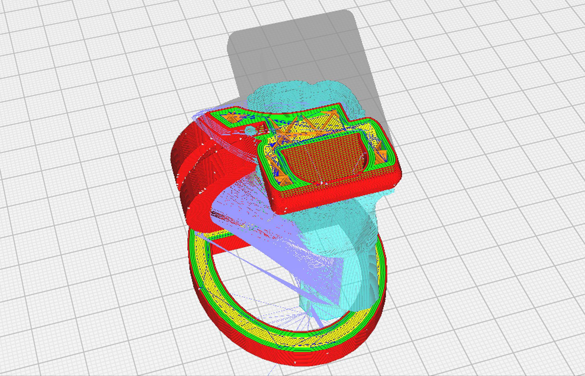
Once we have decided on the quality and density, examined whether any supports are needed, have set the ideal temperatures and printing speed, and determined the most ideal orientation for our print, all we have to do is press the slice button. Then, after some calculations, the software prepares a sliced version of the model. Here, we can view the sliced object layer by layer. We can check whether the settings are correct, whether the wall thickness is ideal everywhere, whether the amount of infill is sufficient, etc. We also get an estimate on how long the printing would take, how much material is required, and in some cases we can even get an estimate on how much the final print itself costs, based on the amount of filament used. If we are not satisfied with these, we can play around and adjust the settings to make them as ideal as possible.
If the result of the slicing meets all our requirements, we just have to press the export button. The software then creates a .GCODE file in the previously specified location on the computer or directly on an SD card. This file contains a block of code that our printer can interpret. The printer’s control system is similar to programs generated for CNC machines. It is made up of various parameters and coordinates that determine the entire printing process. In this code, within the framework of certain slicers, or even by opening the file separately in a text editor, we can modify the code by hand and specify extra processes, e.g. pausing. Meddling directly in the code is only recommended for experts, because if we enter an incorrect code somewhere, we can even damage the printer.
Printing
When we have our .GCODE file, we then have to copy it on any data carrier we prefer (SD card, USB pendrive - depending on what our printer supports) and then plug it directly in the printer. After this, on the control panel of the printer we have to start the printing. The interface, the steps to starting a print job differ depending on what printer we use, but the further processes are mostly the same.
After we hit start on printing, the printer reads the .GCODE file from the data carrier and starts processing it. If there is a filament sensor on the device, it checks whether any filament is threaded. If there is none, the process stops and the user is informed that no filament has been detected by the sensor. If everything is fine in terms of filament, it starts heating the system to the temperatures specified before: first, the print bed, then when the bed has reached the working temperature, then the extrusion head will be brought up to temperature as well. When everything reaches the desired temperature, the nozzle will go home. Going “home” means that the printer sends the head and bed to 0 on all three axes (which axes the head and bed move on depends on the device), i.e. it sends the units to their starting positions, hence the term home. After “home”, it is worth removing the material left in the nozzle from the previous print, which is why the print head usually draws a line on the edge of the bed. As soon as the previous filament emptied out, and there is fresh, clean material in our nozzle, printing can begin. Then all we have to do is sit back and wait for the miracle to happen.
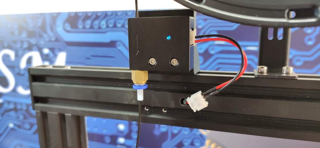 Filament sensor
From filament rolls to final product
Maybe it's not as much of a miracle as it seems at first? Let's see what exactly happens during printing.
Filament is usually sold in rolls. The many meters of plastic filament thread is rolled up on a drum. We have to thread this into our printer. To be more specific: if there is a filament sensor on our device, we have to thread the filament through it, and if not, we have to thread it directly in the extruder, i. e. the filament feeder. We distinguish two types of extruders:
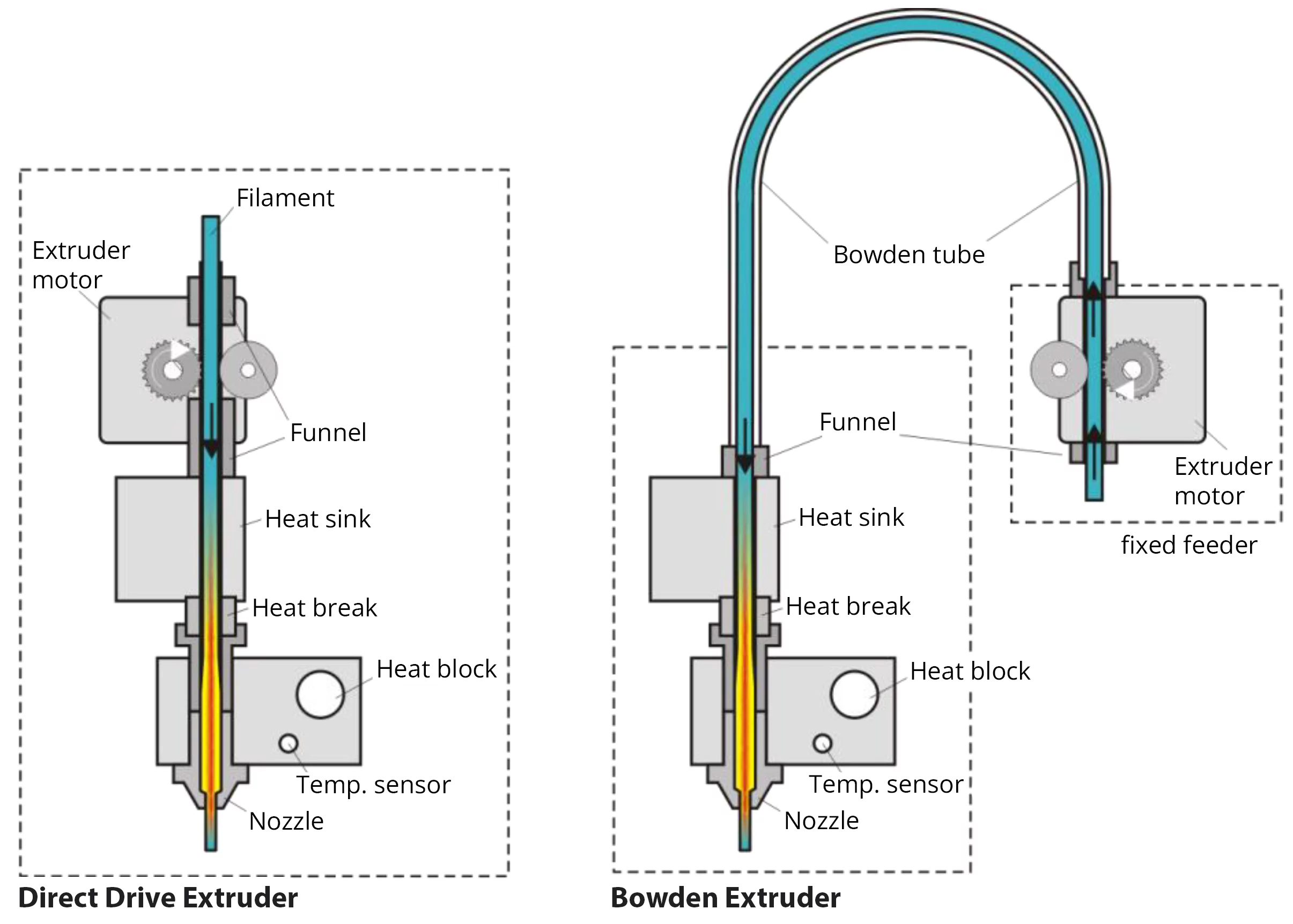
- Direct Drive Extruder: In this case, the extruder motor is located on the printer head and we directly thread the filament in here.
- Bowden Extruder: In this case, the extruder motor is located separately from the printhead and is then connected to the head with a plastic tube (bowden).
From here on, the extruder head takes control. A pair of cogs are powered by a “stepper motor” which feeds the filament in the hot end. This is the part of the device where all the magic happens. It has four main parts:
- Heatsink: This prevents the incoming filament from absorbing the heat from the hotend and softening before reaching the rib itself. This fin is cooled by a small fan.
- Heat break:This is a small tube, part of which runs in the heatsink and part in the heater block, thus connecting the two elements and creating a thermal diffusion break from the block to the fin.
- Heat block: An aluminum block that houses the nozzle, a heater and a temperature sensor. This is where the filament is melted and, thanks to the sensor, the temperature is maintained.
- Nozzle: This is basically a small tube with a narrow end where the melted filament gets pressed out. Its upper stem is threaded into the heating block, and the lower stem is hexagonal so that it can be unscrewed in case of replacement.
The printing process can be described with the following steps: the extruder funnels the filament through the heatsink and the heat break into the heat block, where the filament melts, and the pressure created by the incoming filament squeezes out the molten material from the narrow nozzle. The heated nozzle is tapered to a very small point, so it can be precisely controlled. This extruded, molten material must be cooled, because if we let it cool on its own, it will remain remotely soft for longer, so deformation can occur, and thus the layers won’t be able to fuse together properly. To remedy this, there is one or more fans on the extruder head, which blow cold air through a channel, directly under the tip of the nozzle, thus when the molten material leaves the nozzle, it solidifies immediately. The solidified material is still warm enough to stick to the bed, but no longer warm enough to be malleable and flow. From here, the first foundation layer and additional outlines of our final product can be printed, and then the next layer can be added. To add the next layer the print head or print bed (depending on what printer we have) moves along the Z axis by one layer thickness and prints the next layer. It is important to note, that when the machine prints a new layer on top of a previous one, the heat coming from the heat block heats up the lower layer enough to soften it for the new layer to adhere. This is how the physical bond between two layers is created.
We can make unique and complicated shapes because of the printer being able to move along 3 axes. X, Y and Z. The X and Y axes determine the horizontal plane and the Z axis determines the vertical direction. The printer works layer by layer, printing on one horizontal plane after the other, moving up on the Z axis and then repeating the process until we have our finished 3D object.
A real miracle!
After completing the last layer, the print head sets itself to 0 on the X and Y axes, then it indicates on the display that it has finished printing and starts cooling the system. If we are talking about a heated print bed, it is worth waiting for it to cool down too, because if we want to remove the workpiece while it is still warm, it might be difficult, because as intended the workpiece sticks to the bed, and even if it is removed, there is a high chance that deformation may occur in the still warm final product (the degree of possible deformation depends on the temperature of the bed). As soon as the bed has cooled down, the workpiece comes off relatively easily, often on its own.
After removing the printed object from the bed, if we used any supports, the next step is to remove them. Often the supports can be removed simply by hand, but sometimes we might need to use a plier.
After removing the supports, if necessary, we can further perfect our 3D print by e.g.: sanding, painting. After that, the only thing left to do is to admire the product of a tool with such genius engineering.
If you are interested in what should be taken into account in case of filament printing, what are the tricks that make our work easier, follow our blog, because we will talk about those in a follow-up post soon! ;)
If you’d like to read more about 3D printing please refer to the #3dnyomtatas tag.
Written by Cs. Krisztián, translated by F. Flóra.